
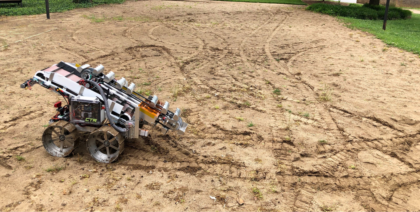
I worked with the Vanderbilt Robotics Team to build a remote controlled mining robot for competing in the 2018-2019 NASA Robotic Mining Competition . I served as the team programming lead and was responsible for all the software development for the project. Some parts of the project didn't go so well - we were behind schedule all year, didn't get the robot built until a week before the competition, didn't have time to test/integrate any autonomy software, and our robot got stuck in a hole and started smoking at the competition. On the other hand, a lot of stuff went really well - we came up with a viable robot design, built it, got manual control working, wrote a lot of autonomy software, and were able to drive around and start digging at the competition! Plus I easily learned more from this project (and the USLI project ) than from all my college classes combined. Also it looks really cool.
The Goal
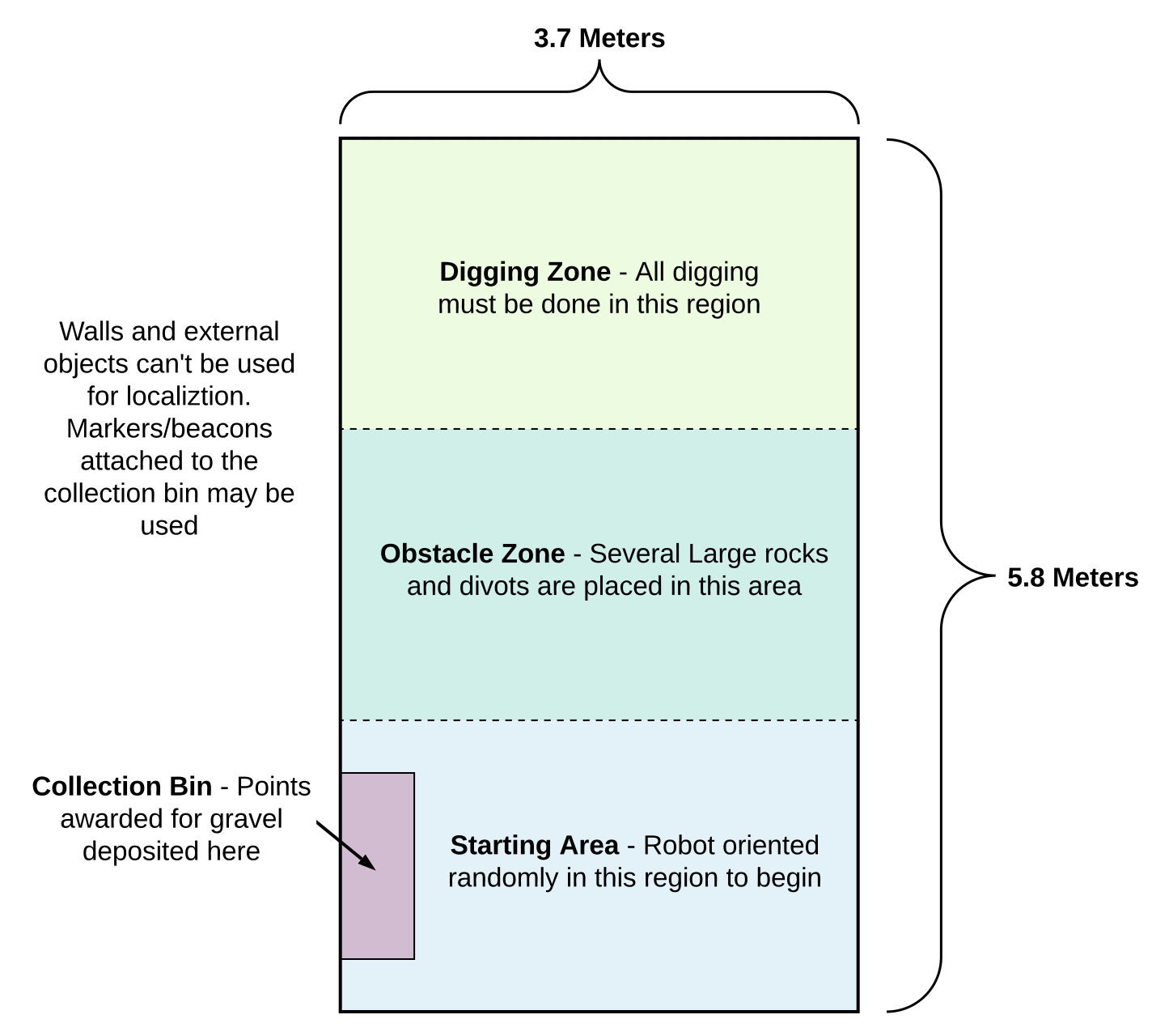
The NASA RMC rules are extensive but the quick version is roughly as follows: Design a robot, no larger than 1m x 1m x 0.75m which weighs less than 75kg. The robot will be placed in a ~12ft x 20ft arena, oriented randomly, near a large metal collection bin. The robot must drive to the opposite side of the arena, collect as much buried gravel as possible, drive back to the collection bin, and deposit as much of the gravel in the bin as possible. The gravel is buried under 30cm of powdered surface material. The robot gets 10 minutes. Points are awarded based on the weight of the gravel you collect (surface material doesn't count towards the weight) the degree of autonomy that the robot exhibits, and some other characteristics of the robot like weight, dust-tolerance, and power efficiency.
Design Process
The team was divided into three subteams: mechanical, electrical, and programming. The teams mostly met and worked together during the early brainstorming phases, then gradually became more independent as the year went on. The design process consisted of 4 general phases - (1) early brainstorming (2) preliminary design, culminating in preliminary design review (3) final design, culminating in critical design review, and (4) fabrication / assembly / testing phase. In reality we only loosely followed these, and different parts of the team were on different schedules but we did have an actual PDR and CDR where we presented our design to our faculty advisors for feedback.
The design process went well for the most part - the biggest problem was that there simply wasn't enough urgency at the beginning of the year, leading to a serious time crunch in the last month of the project. The competition was scheduled for early May, and we didn't have the robot fully assembled until mid to late April. We weren't testing our software on the physical robot until about a week before the competition. This meant that we really had no time to fix things that didn't work, iterate on our design, or test critical systems under different conditions. I'm confident that with 1-2 extra months for the project, we could have had the robot working well enough to at least collect and deposit a few kg worth of gravel at the competition. I discuss more of what I learned from RMC and USLI in [this] blog post
Final Design
Frame &Drive
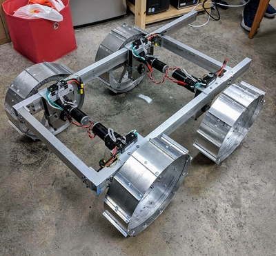
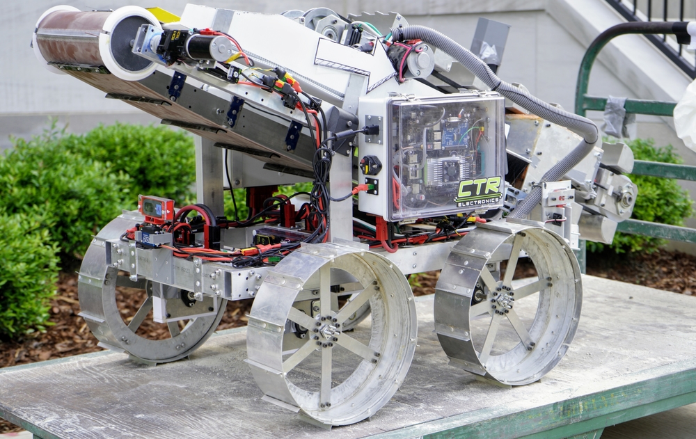
The robot frame is made of 1" x 2" rectangular aluminum extrusions, connected at the corners with L-brackets. This provided plenty of strength and was easy to manufacture and assemble. Wheel design is a little tricky for this competition because of the properties of the surface material, BP-1, which is meant to simulate lunar regolith. It's dense and powdery - I heard it described as being like flour but more dense (it's hazardous to breathe so I never got a chance to actually touch it). The wheels need to be flat and wide enough that they don't dig through the BP-1 as they spin, but they also need to have enough traction that they're able to propel the robot. The design we chose, based on successful designs from other teams in previous years, uses wide, large-diameter wheels with grousers spaced evenly throughout. This wheel design seemed to be adequate as we had no difficulty driving around at the competition and could even traverse small and medium sized rocks. We drove the wheels with Geared DC motors and Talon SRX Motor Controllers.
Digging &Depositing
Digging was the hardest mechanical design challenge. Given the size and weight constraints of the robot, 30cm is quite deep to dig, and gravel is not a forgiving material to dig through. We spent close to a month brainstorming digging strategies. We ultimately narrowed it down to a "single large scoop" design and a "many small scoops on a chain" design (aka "bucket chain"). The large scoop has the advantage of being mechanically simpler with fewer parts and fewer failure points. However, the force required to dig with a large scoop is hard to counteract without making the robot very heavy. The advantage of the bucket chain is that each individual scoop does less work - however this design has more parts and more failure points. We chose to pursue a bucket chain design - most of the successful teams in past years seemed to be using some variation of this design so we knew it at least could work. Being a new team (this was Vanderbilt Robotics's 3rd year as a team and 2nd year doing this competition), we decided to prioritize getting something that worked over coming up with a novel design.
We did manage to create a *mostly* working bucket chain. The entire appendage that holds the bucket chain can hinge forward and backward and move up and down - this is necessary for reaching the required depth while still being able to retract to fit within the size constraints. Each part of the system worked decently enough, but the whole thing ended up being less rigid than it should have been and a little under-toleranced. We were able to dig successfully with it a few times out of buckets in the shop. It dug nicely through the surface material but when it hit gravel, it felt like the whole thing could fall apart at any second. We had a variety of problems with gears slipping / shearing, things flexing too much, motors stalling, and other stuff like that. I think if we'd had a chance to rebuild the whole thing a second time, we could have worked out most of the issues and made something pretty reliable.
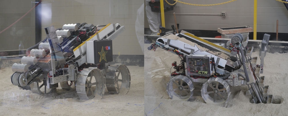
The bucket chain pulls up material and dumps it on to a conveyor belt that runs along the length of the robot. While the chain is digging through the surface material, the conveyor belt spins quickly, dumping it off the back (surface material doesn't get weighed). Once the scoops reach the gravel, the conveyor starts spinning more slowly so that it fills the belt with gravel. The bucket chain then stops and retracts so the robot can drive back to the collection bin and run the conveyor again to deposit the collected material.
Electrical
The electrical system consists of (1) the main battery and other power distribution components (2) motors and speed controllers (3) the main computer, and (4) other sensors for autonomy. Power comes from a big LiPo battery. We had a handful of breakers and a master E-stop so that we could easily disable power for individual subsystems or the whole robot. We used an Nvidia Jetson TX2 as the main computer. We were allowed to place a router near the arena so we could use WiFi for all our communication. As for sensors, we had a camera mounted on a servo attached to the back of the robot and an XBox Kinect mounted at the front. We didn't end up using these at the competition though as we didn't attempt autonomous operation.
The electrical system was really well designed and frankly quite beautiful. All the sensitive electronics are contained in air-tight boxes to keep the dust out, and all the wires are well-organized and secured out of harm's way. To me it was the most impressive part of the robot. Credit to Joey Holliay , Andrew Mathias, and the rest of the electrical team for their excellent work on that.
Software
The plan
We used Robot Operating System (ROS) to structure the robot code. ROS let us write the software in a modular way, with discrete blocks of code for each task and convenient channels for passing information.
Our goal was to implement both manual and autonomous control software for the robot. Under manual control, the navigation and digging systems could be operated remotely using a handheld controller. The autonomous control software would operate the robot without user input, sending enough information back to the operator that they would know if the robot was behaving as expected. We would start the run autonomously and take manual control if the autonomy code started to malfunction. While we made a lot of progress on the autonomy software, none of it was ready to be deployed on the robot by competition time, let alone tested enough that we'd be comfortable using it.
Manual control
We did, however, get manual operation of the robot working. This took input from an XBox controller, converted it to driving and digging commands, and sent those commands to the robot. In ROS terms, one node published the controller states, another converted the analog stick positions to linear and angular velocities (and then individual wheel speeds), and another which interfaced with the speed controllers to control the motors. The digging system was actuated by four different motors - bucket chain, hinge, linear slide (depth control), and conveyor belt. Each of these systems could be individually operated from the controller as well. We also wrote a routine that would perform the whole digging sequence automatically to make the control a little easier for the operator. The interface still wasn't great, but it was good enough for the robot to be usable at the competition.
Autonomous control - overview
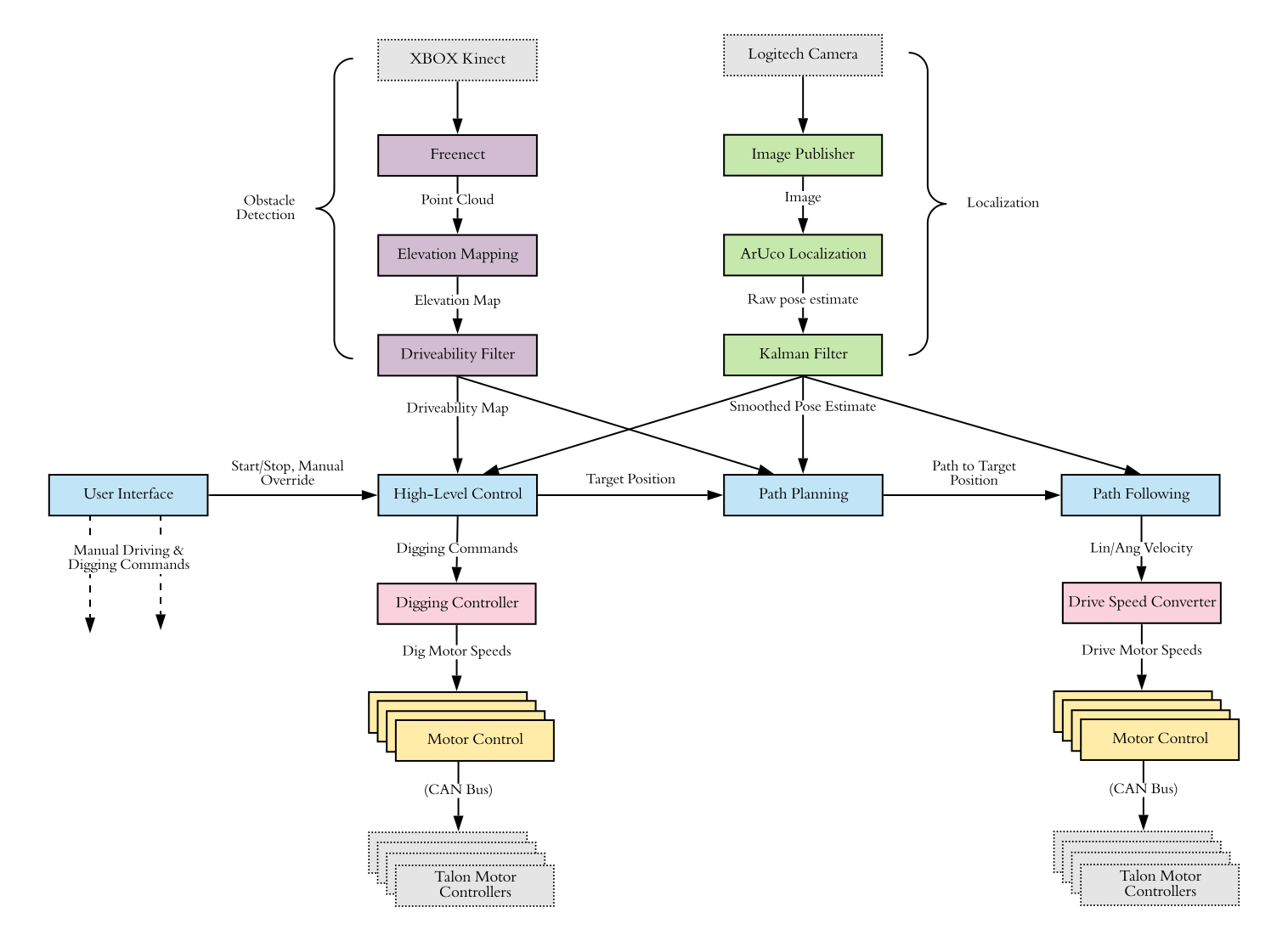
The general idea behind the autonomy software was as follows. The localization module would determine the pose of the robot relative to a fixed landmark and update the pose as the robot moved throughout the arena. The obstacle detection module would scan the area around the robot and determine the positions and sizes of any large rocks or divots in the arena. The path planning module would use the pose of the robot and the information about the obstacles to compute safe routes to and from the digging area and collection bin. The navigation (path following) module would control the drive motors to move the robot along the desired path. The digging module would coordinate the operation of each part of the digging system. Finally, a high-level planner would determine what action (travelling, digging, depositing, etc.) the robot should be taking and coordinate the other modules accordingly. Below is a slightly simplified version of the ROS network that illustrates the overall architecture. Start with the blue boxes and follow them left to right.
Localization
The rules prohibited using the walls or anything outside the arena as an aid for localization, but they allowed using beacons or markers attached to the collection bin. We considered a variety of localization approaches but ultimately decided to attach ArUco fiducial markers to a board that we would hang from the collection bin. OpenCV provides functions for inferring pose from images using these markers so this was an almost out-of-the-box solution available for free. We attached a camera, mounted on a servo, to the back of the robot. The servo effectively gave us a wider camera angle, letting us view a region close to 180 degrees without turning the robot. The robot would rotate in place at the beginning of the run until the marker board was detected. Once the pose relative to the marker board was obtained, the robot would then start navigating to a digging location. The collection bin would always be in the same place in the arena, so knowing the robot's position relative to the bin gave us the absolute position of the robot in the arena.
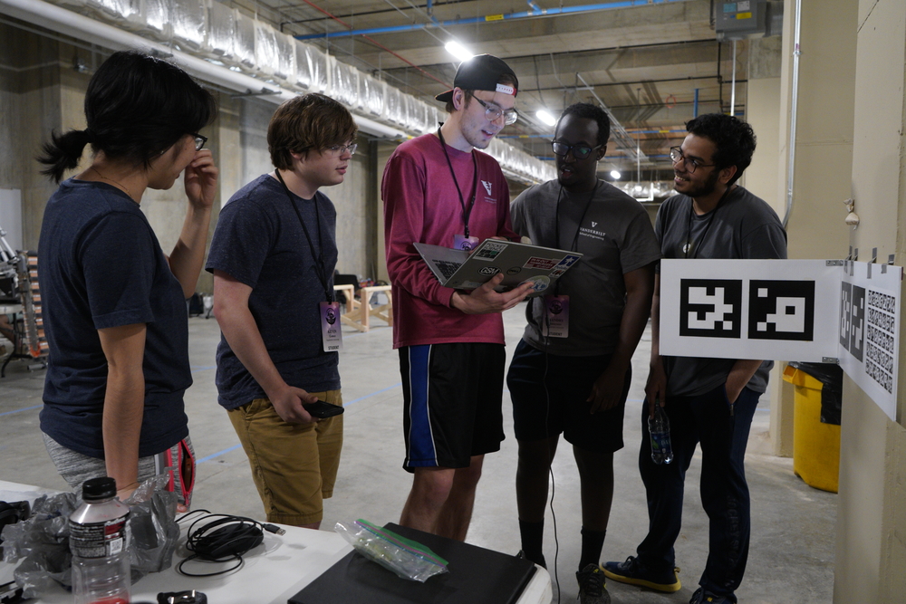
The localization code was very close to working - we used it successfully with single markers at short to medium distances. As we added more complexity by using multiple sets of markers positioned at different angles (see image), increasing the distance, and accounting for the angle of the camera servo, the pose estimates started getting really jumpy and other problems arose that we weren't able to resolve by the time of the competition. I'm certain that with another month we could have gotten the localization code working seamlessly.
Obstacle Detection
Obstacle detection was where we made the least progress. This isn't surprising since it's probably the most complex part of the autonomy process. We also kept deferring it because we figured the robot could probably still survive a run without checking for obstacles (the obstacles weren't so big that they were totally impassable). The most promising approach we tried was to use a depth camera (in our case an Xbox Kinect since we had one lying around) to produce a point cloud which we then could pipe through an open-source elevation mapping ROS package to get a terrain map. This would produce a 2D "image" where the value corresponded to the elevation at that point. With the elevation image, we could check for points with a slope above a safety threshold and classify the region near those points as unsafe. This would give us a "driveability map" that could be used by the route planner to make sure the robot followed a safe path. The theory of this seemed sound but each part of the process proved to be more challenging than expected and we never came particularly close to getting it working
Path Planning and Following
The path planning module assumed that the obstacle detection module was sending it driveability maps, cm level grids (images) of the arena where unsafe regions were marked as '0' and everything else was marked as '1'. It also took the current robot pose as input from the localization module and the goal position as input from the high level planning module. It then used A* search to compute the shortest safe path from the current position to the goal position and sent that path on to the path following module. A new path was computed only when a new goal position was specified or a point on the current path became classified as "undriveable."
We used the pure pursuit algorithm to accomplish path following. This algorithm takes as input a path and the current position of the robot and outputs an angular and linear velocity. In a nutshell, it computes the closest point on the path to the robot, looks ahead a certain distance, and determines the arc the robot needs to take so that it will reach that point. From that you can determine the linear and angular velocity for the robot, and in turn, the individual wheel speeds. A good way to conceptualize this algorithm is to imagine a string attached to the front of the robot that's being pulled along the path. If you use a large lookahead distance, the robot won't stick to the path as well but it will also tend to oscillate less. A smaller lookahead distance keeps the robot right on the path but can lead to oscillation around the path.
We got both path generation and following working in simulation, though we were never able to test them on the robot since we didn't get localization working. In the simulator at least, we could supply an obstacle map, robot pose information, and a target point, and the algorithms would successfully compute a path and steer the robot along the path.
High Level Planning
The high level planning (HLP) module was implemented as a finite state machine where different states corresponded to different portions of the mission. This module took the elapsed time, position of the robot, digging state, and commands from the operator as inputs. To control the behavior of the robot, it could send new target positions to the path planning module and new digging commands to the digging module. The figure below shows the primary robot states.
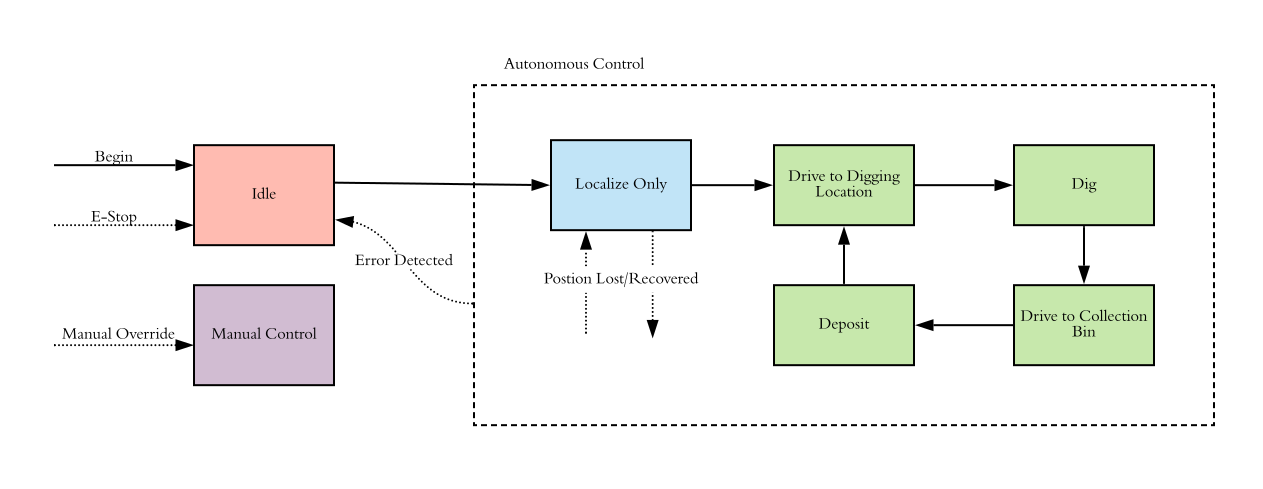
We got the HLP module partially working. We implemented a subset of the states but couldn't finish it in full as we never got localization or obstacle detection working. Using the simulator, we were able to test that the HLP module could properly select new target points, detect when the robot reached them, and manage digging behavior appropriately.
The Competition
The video below shows our first attempt at the competition. We did a second run later but the digging mechanism was disabled and one the wheels wouldn't spin, so it's not terribly interesting. Things actually started out pretty well but then a series of failures crippled the robot. As we were digging, one of the gearboxes in the bucket chain mechanism broke when we reached the gravel, meaning the chain couldn't spin anymore. We had collected a small amount of gravel so we decided to at least try and drive back to deposit what we had. On the way back, one of the wheels went into a divot. We aren't totally sure what happened but somehow that caused the motor and speed controller for that wheel to heat up, destroying them. Most likely, the wheel got jammed and the control loop caused a current spike which fried the components. In any case, that wheel no longer worked. From there, there wasn't much we could do, so we ended the run shortly after.
Notes
- If you want to see a mining robot that actually works, check out the University of Alabama robot (8:11:27 in the video). Alabama has dominated this competition for years - their robot is fully autonomous and completes several mining runs in the 10 minute window. North Dakota State's robot (31:50) was great as well (they use a single big scoop), as are many others.
- One of the biggest mistakes I made was not building a small robot to work with while the real one was being built. A little 4-wheeled robot with a camera and Raspberry Pi would've been a great platform for testing all the code (other than digging). Not only that but I think it would have been a helpful motivator for the whole programming team - I think many of us were somewhat discouraged because none of the code we were writing seemed to do anything since we weren't deploying it on a robot until right near the end. This also would have eased the process of porting stuff to the final robot when the time came.
- I would have loved to work on this project a second year to try and build off all our progress. Unfortunately I only joined the team my Junior year. Senior engineers at Vanderbilt all do a year long "senior design" project which is a huge time commitment so I wasn't able to keep working with the robotics team the next year. I did get to work on a different awesome project instead though!
- Because most of the programmers were younger students with little or no robotics experience, a big part of my role as programming lead, especially early in the year, was teaching them the "fundamentals of programming for robotics." This was very challenging for me, not because they were bad students but because, while I did have a decently strong robotics background by that time (for an undergrad at least), I was, and still am, far from an expert. On top of that, I'm not the most comfortable or clear speaker in general. I did my best to teach the team about path planning, localization, microcontrollers, PID, ROS, Linux, and whatever else came up as the year went on. I'm not sure I did a great job of it (in fact I'm sure I didn't), but I learned a huge amount about teaching, speaking clearly, explaining complex topics, and sharing the excitement I feel about robotics with others. It was an experience that was frequently very uncomfortable for me in the moment, but one that I'm incredibly glad that I stuck with as I look back.
Acknowledgements
This project wouldn't have been possible without the collective effort of the Vanderbilt Robotics Team . Alex Barnett and Swapnil Pande deserve extra credit for running the team as president and vice president respectively in addition to their work on the robot. This was only VUR's 3rd year - it quickly grew into an inclusive, highly regarded student organization in no small part thanks to Alex and Swapnil. Tom Withrow and Alan Peters served as faculty advisors and provided invaluable feedback throughout the year. Phil Davis ran the machine shop and helped us with all our fabrication needs. Vanderbilt Plant Operations gave us a home and let us do our thing when nobody else would.
The original NASA RMC for 2019 was cancelled halfway through the school year due to an untimely federal government shutdown. In response, University of Alabama stepped up and, with the help of Caterpillar , hosted the competition on their campus. They did a phenomenal job and gave hundreds of students the opportunity to demonstrate their work. We are immensely grateful.